- Home
- Learn Linux
- Learn Electronics
- Raspberry Pi
- Programming
- Projects
- LPI certification
- News & Reviews

Google Ads
Here are some common optoelectronic components.
The light emitting diode, usually known as LED, is a special diode constructed so as to emit light when a current flows through it.
Connected in series with a resistor to prevent damage to the LED. Typically the forward bias for the LED is 2V. The LED normally operates with a forward current of about 5mA to 40mA. There is normally a significant change in brightness between 5mA and 15mA after which the change is less noticeable. An LED has a very low resistance when conducting and a resistor is normally needed to limit the current to no more than 40mA. This is not required (although still recommended) for the Arduino as the output of each of the pins on the Arduino is less than maximum current for the LED.
In series with resistor R1 the voltage across R1 is normally the input voltage - the forward voltage of the LED (2v). Using R = V/I we can determine the appropriate resistor required based on the supply voltage. Typically a resistor of 220Ω or 330Ω is used for a 5V power supply giving a current of about 10 to 15mA.
Some packages can support multiple colours by integrating different colour LEDs into a single package. A typical tri-colour package may contain a Red and Green LED in a single package with a single cathode connection. The actual colour can be varied by changing the current through each LED which changes the intensity. LEDs are also available with Red, Green and Blue (RGB) in a single package which provides a wide range of colour options.
The table below shows some typical voltage and current values for a 5mm LED. The actual value depends upon the specific LED, if in any doubt then check the datasheet for your specific LED.
| LED typical values | ||
|---|---|---|
| Colour | Voltage | Current |
| Red | 2.0 V | 20 mA |
| Orange | 2.0 V | 20 mA |
| Yellow | 2.1 V | 20 mA |
| White | 3.3 V | 20 mA |
| Green | 2.2 V | 20 mA |
| Blue | 3.2 V | 20 mA |
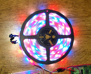
To allow standard RGB LEDs need to be individually controlled would need a lot of individual connections. To overcome this many LED strips are now available with integrated controllers for each LED. These allow a strip of LEDs to be controlled from a single control signal. The LED modules can be purchased individually, but are commonly supplied on a strip with the LEDs and controllers included. Popular LEDs include the WS2811 or WS2812 RGB LED controllers which are integrated into the LED module, or some are available with the IC next to the LED such as the WS2801. AdaFruit refer to their range as NeoPixels, which specifically refer to those with the WS2811 or WS2812 ICs, for other suppliers you will need to check the details of the controllers.
The RGB LED modules based around the WS2811 / WS2812 are connected together in serial with the output from one LED going to the input of the next LED. Each LED is provided with the instruction based on it's position from the controller end.
According to the datasheet for the WS2812B (made by WorldSemi) each LED module is controlled using a 24 bit serial signal which contains the numerical value for each of the colours ordered as GRB (high bit sent first). The GRB value for each subsequent LED is also sent in the same block of data. Each LED controller strips off the 24 bits used to set its own LED display and then forwards on the rest of the bits through through data out so that it can control subsequent LEDs. A minimum 50 microsecond delay is then used as a reset signal to signify the end of that signal.
Power is normally 5V and a single supply is provided for the entire length. The stated current draw can depend upon the LEDs used, but is typically around 60mA per LED. Assuming a 5 meter long strip with 30 LEDs per meter this would need a power supply of 9A at 5V (45W) if all the LEDs are at full brightness. In practice I have found that the actual power usage can be much lower. For example I have a RGB LED strip rated at 7.5W per meter, which should have needed a 7.5A supply for a 5m long reel. In reality I measured the current to be nearer 2.5A with all LEDs on full brightness (white). This may vary between different manufacturers. I recommend using a power supply that meets the minimum specification or at least testing the actual draw to ensure you don't risk damaging the power supply - or worse!
The timing of the signal needs to be fairly accurate. If a signal is interruped (such as in a Raspberry Pi using the standard GPIO) then the gap can be interpreted as a reset which can result in the LEDs being out of sync. This can be overcome using a PWM signal which can be generated by many PIC controllers and is available on GPIO 18 on the Raspberry Pi (note that the Raspberry Pi needs a voltage shift to convert the 3.3V output of the Raspberry Pi GPIO to a 5V data input for the LED modules).
The optoisolator / optocoupler is used to provide electrical selection between devices. This can be used to pass a signal to a part of the circuit operating on a different voltage, or to isolate parts of the circuit where it is necessary to provide physical separation.
The switched output is created as a bipolar junction similar to a transistor, but uses the optical trigger instead of a current applied to the base. There are other isolators that use a triac connection in-place of the bipolar transistor (see below).
The optotriac isolator is similar to the optoisolator, but switches through a triac instead of a bipolar transistor.
Please view the copyright information regarding use of the circuits.

