- Home
- Learn Linux
- Learn Electronics
- Raspberry Pi
- Programming
- Projects
- LPI certification
- News & Reviews


MOSFET stands for Metal-Oxide-Silicon Field Effect Transistor. It is similar to a transistor switch. A MOSFET can also be used for switching larger currents based on a small input signal. This can be particularly useful when switching larger loads from a microcontroller or Raspberry Pi GPIO port.
This video explains how a MOSFET switch can be used to switch large loads including disco lights.
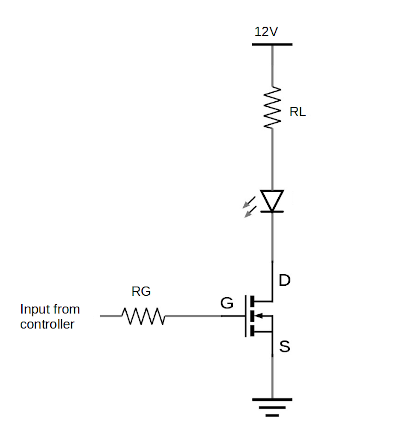
The circuit below shows a common simple configuration for a MOSFET switch circuit. It comprises of one N-channel MOSFET, and depicts two resistors. The resistor RL is not normally a resistor, but represents the resistive value of a device that is being switched. This could be a lamp or relay or some other device that needs a larger current than the input is able to drive directly. The resistor at the gate RG is a resistor used to prevent damage to the device controlling the switch, such as a Raspberry Pi or microcontroller. Details of how to determine the size of the resistor are explained below.

The MOSFET has three pins. The drain, the source and the gate. These are labelled D, S and G in the diagram. The gate is used to switch the MOSFET on and off. With no charge on the gate (set to 0V) then the MOSFET will be switched-off and no current will flow between the drain and source. When there is a positive charge at the gate then the MOSFET switches on and a current can flow between the drain and source.
The gate of the MOSFET has a high impedence (for a DC signal static signal that's the same as resistance). This means that the amount of current flowing through the gate source junction will be very small. On that basis then you should not need a resistor at the gate. However one of the things about the MOSFET is that they have an effective capacitance between the terminals. This means that when a voltage is applied to the gate then there will be an initial rush of current into this capacitance. The resistor is therefore included to protect the driving device (such as a Raspberry Pi or microcontroller). This is less important with small low power MOSFETS, but for higher power MOSFETS then this is more important.
Whilst the aim of this is to keep the maths to a minimum we need to use some simple formula to determine the appropriate value for the gate resistor Rb. The key equation used here is Ohm's Law.
To work out the appropriate level of resistor we need to calculate the resistor to limit the current to a safe level. In the case of a Raspberry Pi then that is 16mA which is the maximum for a single GPIO port. The voltage is 3.3V which divided by 16mA gives 206Ω. The nearest resistor greater than that is 220Ω. You could use a larger resistor, for example 470Ω which would help prevent against the maximum of 50mA across all gpio pins if multiple MOSFETS are switched on simultaneously.
This can be seen in the Disco Light project.
Please view the copyright information regarding use of the circuits.