- Home
- Learn Linux
- Learn Electronics
- Raspberry Pi
- Programming
- Projects
- LPI certification
- News & Reviews

Google Ads
The Micro:bit is a great device for learning programming. One limitation is the limited display provided by the 5x5 LED matrix. This can be used to display scrolling text but it's difficult to read and far from user friendly.
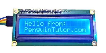
In this guide I will show how you can use an LCD display to show text messages to users. Through this you can create a stop watch program which uses the display for showing elapsed time.
This video gives an overview of the steps taken in programming the micro:bit. This uses the Microsoft block based editor MakeCode, and I also shown what the code looks like in JavaScript. In a future video I'll also show how this can be programmed using Python.
You will need the following:
For this example I used a 1602 LCD display. The code refers to 16 characters per row and 2 rows in total. You could use other models such as a 16x4 which would also work.
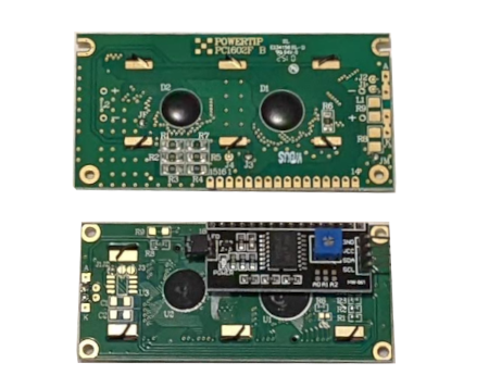
It is important to get one with an I2C adapter. These are needed because the LCD display takes parallel data and so would use up many of the pins of the MicroBit. The I2C adapter allows you to instead send the data as serial data so needs only 2 pins (plus ground). The image below shows an LCD display without the adapter and one below with adapter. You can buy the adapter separately but that will need to be soldered to the display, whereas it is more convenient to buy them pre-soldered on. The adapters are normally based around the PCF8574 or PF8574A ICs. These normally have I2C address 39 (0x27) for the PF8574 or 63 (0x3F) for the PF8574A. If you want to connect multiple devices then you can change the address using solder pads on the bottom of the board.
I have created a separate guide which explains what I2C is and how it can be used.
The LCD display needs a 5V power supply. This is higher than the 3V power supply available on the micro:bit pins. Some breakout boards include 5V from the USB connector, but if not then you will need a separate power supply. In my case I used a USB lead with a micro-USB breakout connector. If using a separate power supply then the grounds will need to be connected together.
The diagram below shows how I wired up my particular setup [click the image for a larger version]. This includes an external micro USB connector which is mounted on a breadboard and used to provide the 5V power needed by the LCD display.

The ground of the microbit and the LCD are connected together. Pin 19 from the MicroBit connects to SCL (Serial Clock) and pin 20 to SDA (Serial Data).
The complete code is shown below (click for a larger image):

See the following pages for more information:

