- Home
- Learn Linux
- Learn Electronics
- Raspberry Pi
- Programming
- Projects
- LPI certification
- News & Reviews


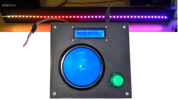
This is an electronics games where the aim is to hit the giant button when the centre LED is lit up. This features a NeoPixel strip with 44 LEDs, with the lit LED moving from one side to the other and back.
It also includes an enclosure designed in FreeCAD suitable for 3D printing.
The code for this is designed to run on CircuitPython. For more details about setting up CircuitPython on a Raspberry Pi Pico then see the link below:
If you find these kind of videos useful please subscribe to my channel : Click here to subscribe.
The first version I created was on a breadboard. Below is a complete list of components used. You could substitute some of these components as required.
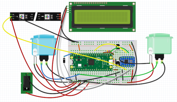
These are connected on the breadboard as per the below diagram. This is explained step-by-step in the corresponding video above.

The power is provided to the Pico through a schottky diode connected to VSYS. For a full explanation about the power connections on the Pico see:
Due to the pull-up resistors included in the LED display a bi-directional level-shifter has been used. This safely converts from the 3.3V GPIO pins to the 5V I2C pins on the LCD display. It also provides a increase from 3.3V to 5V for the NeoPixel strip (advisable, but generally not required). For more details about the problem with I2C and Pull-ups see the link below:
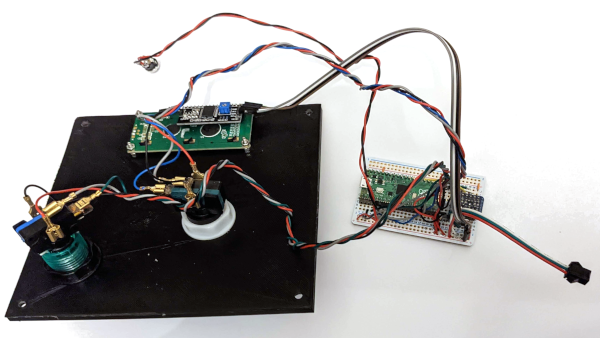
To create a more permanant circuit I used an Adafruit perma-proto 1/2 sized breadboard. I used female headers for the Raspberry Pi Pico and level-shifter which will allow for re-use in future projects. The photo below (partial soldering) shows the schottky diode installed underneath the position of the Raspberry Pi Pico, with a wire soldered to it and protected with heatshrink sleeving.

The complete board also uses a 3-pin JST connector for the NeoPixel strip, male-to-female headers for the LCD display and crimp spade connectors used to connect to the switches and LEDs.

I've explained how to control various devices in my other pages.
The code then creates a main while True loop, which runs forever. Inside that it waits for the giant button to be pressed and then responds accordingly by updating the LCD display. The play will then either continue or wait on the start button being pressed.
You will also need to install the NeoPixel library and the appropriate LCD / I2C library.
Full details are available on my github page:
I've also designed an enclosure in FreeCAD. The files for the enclosure are included in the github download.
The screws used are hex socket head screws. For the LED display I used M2.5 and for the body I used M4. The walls were printed with larger "wall thickness" than normal (through settings in Cura slicer) to allow a screw thread to be added to the base using a M4 threading tap.
It was a long print, expect to take about 2 days for a full print of both parts. The extra thick walls likely contributed to the print time.
I'm always working on new projects
To find out about the updates please:
Subscribe to the PenguinTutor YouTube Channel
and
Follow @penguintutor on Twitter
Please view the copyright information regarding use of the circuits.