- Home
- Learn Linux
- Learn Electronics
- Raspberry Pi
- Programming
- Projects
- LPI certification
- News & Reviews

Google Ads
Building a home server with a Raspberry Pi Compute Module 4 (CM4) on a developer IO board offers incredible flexibility and power. While standard Raspberry Pis are fantastic, the CM4 paired with an IO board provides access to a full-size PCIe slot for lightning-fast NVMe storage. This completely bypasses the physical size limitations of standard Pi HATs, making it an excellent choice for a robust home server, even with newer models like the Pi 5 available.
I've updgraded my home server from a standard Raspberry Pi to a Raspberry Pi compute module with ligtning fast NVME drive, onboard eMMC and exteranal USB drive. This provides a high performance server suitable for use as a home media server, docker containers, NAS and remote GUI interface. This is part 1, setting up the operating system.
The following video goes through each of the steps of setting up and installing the hardware and the operating system.
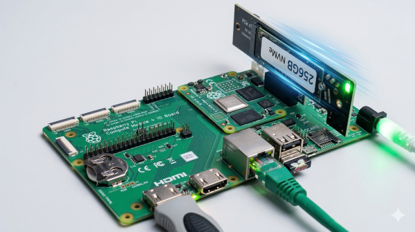
The Raspberry Pi compute module is designed for embedding into hardware projects. As such it needs to be mounted onto another PCB such as a carrier board. In this case I used the Raspberry Pi compute module IO board, which provides a breakout of various input output mechanisms, including a full size X1 PCIe slot. This means that you can insert regular PCIe cards. In my case an NVMe card allowing full size NVMe drives.
Similar capbility is available on the Raspberry Pi 5, but using Raspberry Pi HATs instead, which are usually limited due to the physical size.
Another reason for using this is that I wanted to get additional experience in the use of a compute module, inclusing setup of the eMMC and selecting NVMe boot options.
This module and board was purchased before the compute module 5 came out, but despite that there is one advantage to the compute module 4, due to the hardware support for video encoding. A workaround is to only encode files using a native format that can be handled by the client (such as h.264), but for those with MPEG4 files (such as DivX formatted files) then it can provide realtime hardware decoding preventing stuttering during video playback.
The physical build requires combining the compute module with a carrier board and installing your storage drives. This is shown step-by-step in the video above. Here are details of the physical hardware.
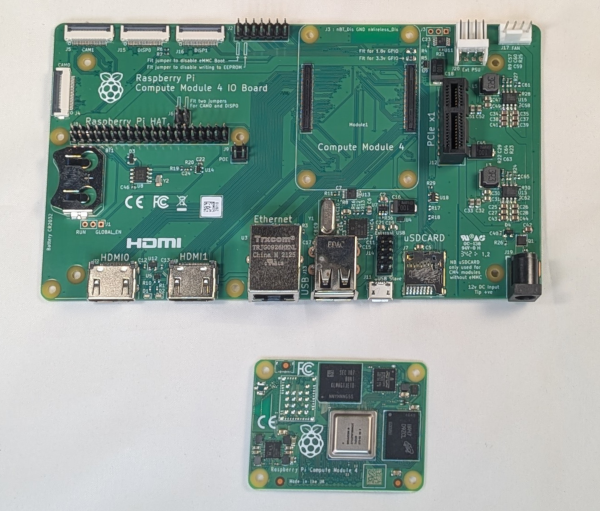
The Compute Module: The core is the CM4 module. These are available with different storage and connectivity options, in my case 8GB of RAM and 16GB onboard eMMC storage. They are also available with built-in WiFi. As mine is going to be connected by Ethernet I opted for one without Wi-Fi.
The IO Board: The CM4 can be plugged onto the official Compute Module IO board using the high-density connectors. This board provides essential peripherals like HDMI, Ethernet, USB, and the crucial PCIe slot.
Power Supply: Power the board using an 12-volt supply. You can however used different voltages if the PCI doesn't need 12 volts. In my case the Raspberry Pi 8V power supply designed for use with the built-HAT.
RTC Battery: Installing a battery for the real-time clock is a great optional step.
NVMe Storage: Install a PCIe NVMe adapter card and your NVMe SSD into the PCIe slot. The Pi's PCIe interface will allow speeds of around 500 megabytes per second, but this is still incredibly fast for a Pi.
Bulk Media Storage: Connect a massive external hard drive to one of the USB 2.0 ports. While speeds will drop to around 30 to 40 megabytes per second, this is more than sufficient for streaming 4K video, MP3s, and photos.
If using a Raspberry Pi 5 then the Raspberry Pi Imager can be used to isntall the operating system direct to the NVMe and update the EEPROM. This isn't available for the CM4 (as the normal Raspberry Pi 4 doesn't include that support), so this setup is a bit more hands-on.
One option is to connect the NVMe device to another computer and transfer the operating system direct to the card. Instead I decided to use a Raspberry Pi solution, using the eMMC on the compute module as a temporary OS to setup the NVMe drive.
You could use the OS lite for a headless server, in which case you could clone the eMMC direct to the NVMe drive. Instead I opted for the full GUI operating system which allows use of the graphical interface.
First download the appropriate image to the eMMC storage. The following is based on the image from December 2025. If there is an updated verson then you can find details on the Raspberry Pi website.
wget https://downloads.raspberrypi.com/raspios_arm64/images/raspios_arm64-2025-12-04/2025-12-04-raspios-trixie-arm64.img.xzThen use the xzcat and dd commands to transfer that to the NVMe drive.
xzcat 2025-12-04-raspios-trixie-arm64.img.xz | sudo dd of=/dev/nvme0n1 bs=4M status=progressI tried to use the OS lite to configure the EEPROM, but due to problems with the EEPROM lock I had problems doing so. I therefore used the PC and usboot and rpiboot commands. Install the jumper back onto J2 and connect to the PC before running the following steps.
On the PC run:
git clone --recurse-submodules --shallow-submodules --depth=1 https://github.com/raspberrypi/usbboot

cd usbboot

vi recovery/boot.config
Replace the BOOT_ORDER with:
# Try NVMe first then eMMC

BOOT_ORDER=0xf25416

PCIE_PROBE=1
Then compile the bootloader and push it to the CM4 using:
./update-peeprom.sh

make

sudo ./rpiboot -d recoveryDisconnect the jumper and micro-USB cable and it should now reboot from the NVMe drive. I enabled RPI connect and used the configuration tool to enable ssh.
As I was not longer using the eMMC I set that for my log storage. Note that this will wipe all data from the eMMC drive. This first step sets up the partition and formats it as an EXT4 file system.
sudo parted /dev/mmcblk0 mklabel gpt

sudo parted -a opt /dev/mmcblk0 mkpart primary ext4 0% 100%

sudo mkfs.ext4 /dev/mmcblk0p1
Copy the logs over (using a temporary mount point).
sudo mkdir -p /mnt/emmc

sudo mount /dev/mmcblk0p1 /mnt/emmc

sudo cp -a /var/log/. /mnt/emmc/
Then set this to mount at it's permanent location using /etc/fstab
sudo blkid -s UUID -o value /dev/mmcblk0p1Copy the UUID from the command above and add the following line to /etc/fstab:
UUID=YOUR-UUID-HERE /var/log ext4 defaults,noatime 0 2The noatime option stops the operating system from writing an update to the last access time on the drive. This reduces the number of writes to the eMMC.
Then reboot
Adding the external drive involved adding the drive to fstab using the same steps as above. I used /extdata for my mount point. One thing I found was that due to my userid using a different UID I didn't have the correct permissions. I therefore change the ownership of the files using:
sudo chown stewart:stewart /extdata
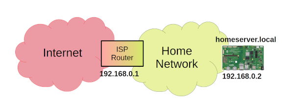
The final stage for this part is to to configure a static network IP address. This makes it easier to find the drive across the network. On the current Operating System (Trixie) this is now configured through network managager.
Find Your Connection Name (normally this is "Wired connection 1")
nmcli connection show
Configure the IP address, gateway (router address) and DNS (router and Google)
code>

sudo nmcli connection modify "Wired connection 1" \

  ipv4.addresses 192.168.0.2/24 \

  ipv4.gateway 192.168.0.1 \

  ipv4.dns "192.168.0.1,8.8.8.8" \

ipv4.method manual
Then restart the network connection. The network connection will drop at this point and you will need to reconnect.
sudo nmcli connection down "Wired connection 1" && sudo nmcli connection up "Wired connection 1"Finally I set up a new hostname using
sudo hostnamectl set-hostname homeserverIn future I'll be adding details of how to: enable containers through installing docker, setup a NAS using samba, configure JellyFin as a media server, and more. Please Subscribe to the PenguinTutor YouTube Channel to get notified of future updates.

