- Home
- Learn Linux
- Learn Electronics
- Raspberry Pi
- Programming
- Projects
- LPI certification
- News & Reviews


 In the previous tutorial Getting started with the Arduino we built a simple switch circuit. In this tutorial we'll replace the switch with something more useful a Light Dependent Resistor (LDR).
In the switch circuit we used a digital input to detect when the switch is on or off. The digital input using logic levels to determine whether the signal is on or off. In the real world we will often connect to sensors that will give a different reading depending upon the reading. In this case the resistance of the light dependent resistor changes depending upon the amount of light on the sensor. Whilst it may be possible to use the digital input there are a few issues with doing so.
Invalid voltage range
The Arduino sees a value below 1.5v as a low (off) and above 3v as high (on). Any other value between those ranges is invalid and may result in unpredictable behaviour. This could be avoided by using the sensor through a transistor or FET which has a more distinct switch from off to on.
Toggling input
When the amount of light is at the point where it should just be switching on (or just switching off) then a slight change may result in switching between a high and low resulting in toggling signal. This may result in a fast flashing effect which may be an issue depending upon what the signal was being used for (eg. lighting a Halogen flood light).
Changing light levels
If using a digital input then the light level to activate switch is set by the relationship between the LDR and the resistor in the voltage divider. The only way to change the light level required to trigger the switch is to change the value of the resistance or additional circuitry, for example by adding a variable resistor. Using the analog port allows us to change the values in software as well as, or instead of requiring physical adjustment.
In addition using the analog signal will also allow us to add some additional functionality which we'll look at later.
One of the advantages of the Arduino is that there is a built-in analogue to digital converter (ADC), which is ideal for connecting our LDR.
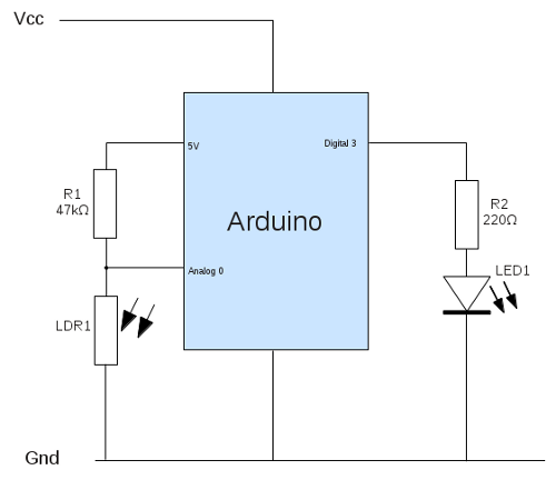
The circuit diagram using the LDR on an analog input is shown below:

This is based on the same as the basic switch circuit in part 1 of the Arduino tutorial. The switch has been swapped for a LDR and a 47kΩ resistor for R1. Instead of connecting to a digital input Analog input 0 is used instead. Different LDRs can have different values, but this particular one goes from approx 15kΩ (in full light) to 2MΩ(in complete darkness). Connected as a voltage divider with R1 uses the formula

This allows gives a range between 1.2v to almost 5v which covers most of the range of the input.
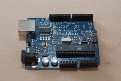
The complete circuit has been build on breadboard, as shown in the photo below.

The next stage is to create the sketch, which is the software to run on the Arduino.
/* Sketch for the ldr light dependent resistor circuitsee http://www.penguintutor.com/electronics/arduino2 for details */ #define INPIN 0 // pin used for input (analog)#define LEDPIN 3 // pin used for output to LED int ledStatus = 0; // LED status (0 = low, 1 = high)int inVal = 0; // variable used to store state of input int switchOn = 300; // value at which we switch LED onint switchOff = 600; // value at which we switch LED off void setup (){ pinMode (LEDPIN, OUTPUT); // Set pin for output digitalWrite (LEDPIN, LOW); // Turn LED off} void loop (){ inVal = analogRead(INPIN); // Read state of the input pin // if LED currently on and go below lower threshold we turn off if (ledStatus == 1 && inVal >= switchOff) { ledStatus = 0; digitalWrite (LEDPIN, ledStatus); } else if (ledStatus == 0 && inVal <= switchOn) { ledStatus = 1; digitalWrite (LEDPIN, ledStatus); }}You can just copy and paste this into the IDE. Then use the upload button to compile and send it to the Arduino (assuming it's connected to the PC). Here's an explanation of what the code does.
Most of the code is the same as the Arduino switch circuit. The main changes are explained below:
Line 7 is a new variable that represents the current state of the LED. I have used 0 for low (off) and 1 for high (on). Whilst I could have used LOW and HIGH (which are predefined) I'm already thinking ahead to some future changes.
Lines 10 and 11 add two new variables which are the values at which the LED should switch on and off respectively. Firstly note that these are now larger numbers than the 1 and 0 we used when using the digital input. The analog input gives a value between 0 and 1023, where 0 is 0v and 1023 is 5v (or the reference voltage if that is set), and the values in between represent the appropriate percentage of the reference voltage. Using my LDR I measured values between about 50 (very bright) and 1000 (very dark).
But why two numbers? The reason we have a different number for on and off is to avoid the problem of the toggling output that I mentioned earlier. If we just turned on and off at 300 say then if there was a slight variance in light levels around that point (as little as 1%) then the LED would turn on and off at an unpredictable rate.
We now use the analogRead function at line 21 to read the state of the input pin (value between 0 and 1023).
The if statement and else statement at lines 23 and 28 are changed so we only change the led status if the led is on and we go below the off setting, or if the led is on and we go above the on setting.
An advantage of using the Arduino (or other microprocessor) is that we can change the behaviour without needing to make any physical changes to the circuit. A simple change would be to change the light levels that required to turn the LED on / off by changing the values of the switchOn and switchOff variables. Or we could change the circuit to do the complete opposite by just changing whether the LED gets switched on or off on a high or low value. If you do change the operation you may want to change some of the variable names as well. I chose switchOn and switchOff because they make the code easier to read, but if you wanted to use this in a different decision process then it may make sense to call them lightThresholdHigh and lightThresholdLow, or something similar. You should obviously update the comments as well to make it clear what the new variable names mean.
Whilst the ability to change the thresholds using code is convenient for our testing, it would not be so convenient if this circuit was deployed as an autonomous circuit without a computer connected. So a useful exercise is to make it so that the user can control what light level the LED comes on at. This can be done using a variable resistor to create another voltage divider circuit on a second analog pin.
If feeling a bit more adventurous (on the coding side), you may want to add the switch circuit from part 1 back using a toggle switch to set whether the LED comes on when it's light or dark.
Finally you may want to look at other sensors that can be used in the potential divider circuit. Just look for those that have a varying resistance for now.
Please view the copyright information regarding use of the circuits.