- Home
- Learn Linux
- Learn Electronics
- Raspberry Pi
- Programming
- Projects
- LPI certification
- News & Reviews

Google Ads
In my earlier projects I created custom Arduino Circuits, KiCAD Arduino PCB design and Model railway automation signals. These have all being based around custom Arduino like circuits based around the ATmega328p microcontroller. In those I recommended buying a ATmega328p with the bootloader pre-installed. This is useful for beginners as it means you can concentrate on the custom circuit, but in this I will go through details of how you can install a bootloader if you buy a basic IC with no bootloader.
The video below gives an introduction to this.
This can be created on a breadboard, but I have also designed a custom PCB shield that can be used as a dedicated programming.
The Arduino Bootloader is a piece of code responsible for running the user code and/or installing new user code. This runs whenever the ATmega microcontroller is powered-on or reset. Essentially it looks to see if the IDE is trying to send new code to the Arduino and if so then it saves that new code to the application area of flash memory. If not then it jumps to the code already in flash memory and starts the microcontroller running. This is an oversimplification, but gives you an idea of how it works.
Without the bootloader then the microcontroller will not be able to do anything unless it is programmed directly using an in-system programmer or similar.
You can get a dedicated AVR-ISP which is an In-system programmer designed specifically for microcontroller chips based around the AVR architecture (which includes the ATMel ATmega series chips). Alternatively you can install code to an Arduino so that it can act as an In-System Programmer. This is known as an Arduino as an ISP, which is what this guide covers.
The below diagram shows the basic setup of how you can program the bootloader using an simple Arduino like circuit created on a breadboard.

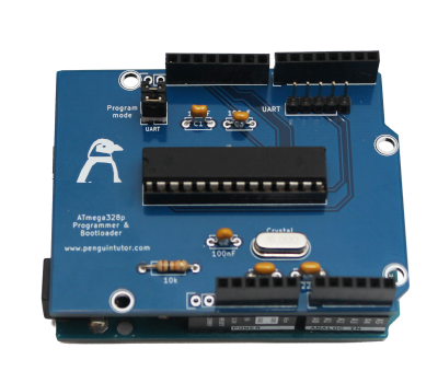
The initial Arduino shield (shown at the top of this page) is based around the same circuit as the breadboard version, but made into a custom PCB. Whilst this circuit works correctly based on experience with the programmer it would be better with a ZIF socket and to have status LEDs. I have therefore created an updated circuit, although not yet had an opportunity to try it.

The following steps should be followed to install the bootloader.
#define USE_OLD_STYLE_WIRINGAfter installing the bootloader you can move the chip into your project and program from there, alternatively:
A comment on my YouTube video asked about the use of the capacitors which I ommitted at the prototyping stage, but then included in the PCB. Here is an explanation of the different capacitors in the circuit.
Capacitor C1 is connected between the UART connector and the Reset pin of the ATmega328p. This is to reduce the risk of any transient noise on that pin from causing a reset.
C2 is connected directly across the supply near to the IC. This is to reduce noise on the power supply going to the ATmega328. Typically these should be as close as possible to the power pin of the microcontroller (pin 7). These are standard for any circuit which uses ICs with one typically next to the supply pin of every IC. You can create a circuit without one, but it is recommended one is included - hence the reason it's sometimes left-out out during a prototyping stage, but then added when creating a permanent circuit.
C3 is similar to C2, but used for the Analog to Digital circuitry within the ATmega. It's connected to AVCC supply connection (pin 20). The supply does need to be connected to the AVCC pin even if not using the A/D converter. If the A/D converter is used then the datasheet recommends using a low-pass filter is used for that supply, so I compromised with an additional capacitor. Looking at the circuit diagram for the UNO then they don't appear to use use either a capacitor or a low-pass filter near to the AVCC pin, but they do include an additional 100nF capacitor as part of the power supply circuitry, it's just not physically close to that pin. So again optional, I'd suggest C2 is more important.
Finally the other two capacitors (C4 and C5) are part of the crystal oscillator circuit used to generate a clock signal for the ATmega328p. The datasheet for the ATmega controllers recommends capacitors between 12pF and 22pF. The 22pF capacitors are commonly available, so I used a pair of them in the circuit.
I'll be adding new projects based around my own custom circuits in future.
I also plan to design my own custom circuit based around the ATMel ATMega328P which I'll be creating on a custom designed printed circuit board (PCB)
.To be notified about future videos
Subscribe to the PenguinTutor YouTube Channel
Please view the copyright information regarding use of the circuits.

