- Home
- Learn Linux
- Learn Electronics
- Raspberry Pi
- Programming
- Projects
- LPI certification
- News & Reviews

Google Ads
The Raspbery Pi Pico and Pico W both have 26 GPIO ports. This is plenty for many projects, but what if you want more? This shows how you can add more GPIO pins through the use of a GPIO port expander based around the MCP23008, and how you can add even more by putting more expanders on the same bus.
This is explained in the video below.
The reason I’m wanting to expand the number of GPIO pins is for my electronic point controller project. In particular I’m looking at creating a panel with LEDs and switches to control the points on the model railway.
There are 4 points which can each be moved into two different positions, which needs 8 LEDs and 8 switch inputs which would use 16 of the 26 pins on the Pico. Also add the 8 point motor outputs and a status LED and I’d just about used up all the GPIO pins on the Pico.
I could do this without the GPIO expander, but I’m also thinking of adding an OLED display and perhaps even the option to add other sensors or outputs, so gave myself some spare capacity.
There are also other ways I could have reduced the number of pins, perhaps using matrix keyboard positions or multiplexing the LEDs, but I also wanted to use a separate PCB for the switch panel and using I²C reduces the number of physical connections between the two PCBs. There are also other integrated circuits I could have used such as the MCP23017 which has 16 GPIO pins, but this allows me to demonstrate how to use different addresses to add multiple devices on an I2C bus.
The MC23008 is an 8-bit GPIO expander. Technically it's known as a MCP23008 ic known as a "MCP23008 8-Bit I/O Expander with Serial Interface", but I2C GPIO expander is a bit shorter. It's also available in an SPI variant known as an MCP23S08. These ICs are also available in 16-bit versions in the form of the MCP23017 / MCP23S17. I could have used one of those instead which would have saved a small amount of money, but this allows me to illustrate how the addressing works.
An important point, which I nearly missed is that port GP7 can only be used for output (on the I2C variants). To overcome this I use the lower 4 bits as inputs and the upper 4 bits as outputs, sharing the 4 switches across the two ICs.
The I2C protocol uses an address for each device. Like many I2C devices part of the address is fixed based on the IC design, but there is also a part of the address that can be configured externally.
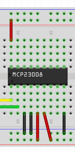
Looking at the IC and counting from the bottom left these are pins 3, 4 and 5. In the diagram shown here pins 3 and 4 are wired to ground, and pin 5 is connected to the +5v supply. This gives a binary representation of 001, or decimal 1. That is added to the IC starting address of 32, giving this particular IC an address of 33 (0x21).
If you power the MCP23008 from a 3.3V supply then you could use it connected directly to the Raspberry Pi Pico I2C ports with pull-ups to the 3.3V supply. If you want to use the IC from a different power supply (+5V in my case) then you will need a voltage level shifter.
I've already provided an explanation of a voltage level shifter. I've used the same circuit as used on that page, but used a 2N7000 for the MOSFET.
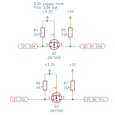
One thing you may notice is that the resistors on the 3.3V side are 4.7KΩ compared to the ones on the 5V side which are 10kΩ. Typically these may be the same size, although having a lower value on the 3.3V supply makes a little more sense to avoid excessive noise. The reason I chose a 10kΩ for the right is because I'm likely to be adding further I2C devices in future which often include their own pull-up resistors. For example connecting an OLED display with a 10kΩ pull-up resistor will reduce the effective resistance down to 5kΩ practically the same as the 3.3V side. The circuit will still work whether another device is added to the bus or not.
The schematic circuit diagram is shown below (click for a larger version).
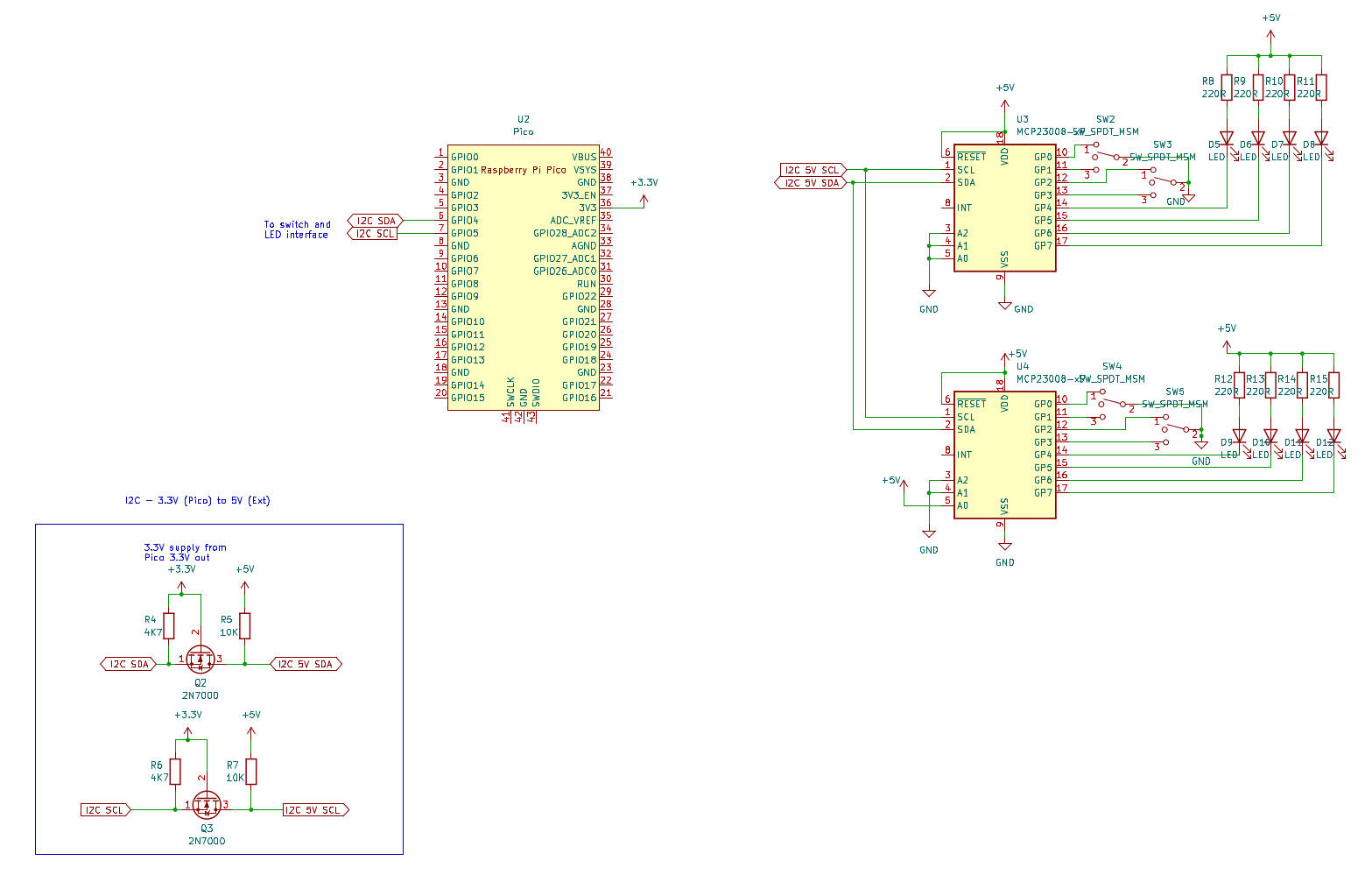
The diagram uses labels to show how the Pico connects to the 3.3 volt side of the level-shifters and then the 5 volt side is connected to the MCP23008 GPIO expanders. There are 4 two-way switches which connect to the GPIO pins GP0 to GP3 and LEDs connect to pins GP4 to GP7. This is duplicated across the second MCP23008 GPIO expander which has pin A0 connected to the positive (5V) supply to give it a different I2C address.
To use this with MicroPython on a Raspberry Pi Pico you will first need to dowload the library file and transfer that to the Pico. Download MCP23008 MicroPython library.
The demonstration code is then included below.
# Test function for use with MCP23008

# This assumes that there are two MCP23008 connected to pins 4 & 5 of Pico

# First has all addresses to 0 = address 32, second has a0 to 1 = address 33

# Also needs mcp23008.py from:

# https://github.com/CrankshawNZ/Micropython/blob/master/mcp23008.py

# For more details see: https://www.penguintutor.com/electronics/pico-mcp23008


from machine import Pin, I2C

from mcp23008 import MCP23008


i2c = I2C(id=0, scl=Pin(5), sda=Pin(4), freq=100000)

# Scan - enable below to check for what addresses are available (decimal)

#print (i2c.scan())

# Or use below for Hex

#addrs = [hex(addr) for addr in i2c.scan()]

#print(addrs)


# Expander 1 = outputs

exp1 = MCP23008(i2c, 32)

# Expander 2 = inputs

exp2 = MCP23008(i2c, 33)


# Set first 4 to inputs with pull-ups

for i in range (0, 4):

    exp1.setPinDir(i, 1)

    exp1.setPullupOn(i)

    exp2.setPinDir(i, 1)

    exp2.setPullupOn(i)


# Set next 4 pins to outputs - set low (turn LEDs on)

for i in range (4, 8):

    exp1.setPinDir(i, 0)

    exp1.setPinLow(i)

    exp2.setPinDir(i, 0)

    exp2.setPinLow(i)


# Read inputs

for i in range (0, 4):

    print (f"Pin A{i} is {exp1.readPin(i)}")

    print (f"Pin B{i} is {exp2.readPin(i)}")
An older version of this said that "GP7 is output only". This was based on an older version of the datasheet by Microchip dated 2004-2022. Other datasheets do not appear to have that entry and the IC does appear to provide full I/O for all 8 GPIO ports. I have continued to use the higher pins for output only, but it does not appear to be required.
I have experienced a problem using the hardware I2C on one of my projects. I've not yet found the reason for this as it did work during testing, but when I installed it on a model railway I experienced timeout errors when trying to use it. In this case I was able to fix it by using software based I2C instead of the hardware based I2C. If you would need to do that then you can replace the i2c instance with the following:
i2c = SoftI2C(scl=Pin(i2c_address[1]), sda=Pin(i2c_address[2]), freq=100000)
You will also need to dd the SoftI2C to the machine import entry at the start of the code.
This is part of my model railway point controller project.
More details coming soon, including integration into computer control system. Please follow my YouTube channel - penguintutor for future updates.
For more information see my Model Railway projects using Raspberry Pi, PicoW and alternative microcontrollers.
Please view the copyright information regarding use of the circuits.

