- Home
- Learn Linux
- Learn Electronics
- Raspberry Pi
- Programming
- Projects
- LPI certification
- News & Reviews

Google Ads
Taking your model railway to the next level often means introducing computer control, and doing it with a Raspberry Pi is both powerful and affordable. In this guide and accompanying video, I'll walk you through setting up JMRI (Java Model Railroad Interface) to manage your layout. Whether you want to control DCC locomotives, automate solenoid points, or manage servos and switches, JMRI is a fantastic open-source solution. Read on to see how I configured it, including specific setup details for MERG CBUS modules.
This video is explains about how to install JMRI on a Raspberry Pi for computer control of a model railway. The example is based around a DCC controller solenoid point controllers, servos and switches.
JMRI is short for Java Model Railroad Interface. It’s open source software which can run on a variety of different hardware. It uses American terms compared to the UK where I live. So it refers to Model Railroad instead of Model Railway, and turnouts instead of points or switches, but other than some different names it’s universal and has good support for different systems used internationally.
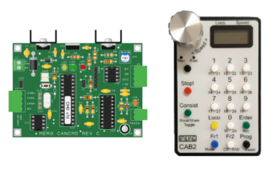
I’ll be using MERG CBUS based modules. The first part of this video applies whatever controllers you are using for your railway buy some of the later parts include some aspects which are specific to CBUS modules. These are from the MERG (Model Electronics Railway Group CBUS) kitlocker.
This explains some of the installation steps. The ones you will need to follow depend upon what you are using. These are all based on the MERG CBUS kits from the MERG Kitlocker, but some of the configuration is the same regardless. The parts involving the FLiM configuration and MMC-SERVER are specific to the MERG electronic kits.
I used a Raspberry Pi 400, which is the model that is combined into a keyboard. It has 3 USB ports providing sufficient for the Raspberry Pi mouse, the MERG CANUSB4 module and one spare port for other accessories (or to attach a USB hub). JMRI will run on a Raspberry Pi 3 model B+ onwards. I'd recommend at least a Raspberry Pi 4 for performance.
I started with a fresh install of the Raspberry Pi OS. At the time of writing this is the 64 bit version of Raspberry Pi OS based on Debian version 12 Bookworm. I first performed an update using
sudo apt update

sudo apt upgrade
I also did some simple configuration such as enabling RPi Connect. This is optional and only required if you would like to connect to the Raspberry Pi remotely.
A Java Realtime Environment is required which can be installed using:
sudo apt install openjdk-17-jre
In future versions of the OS then the version may need to increase.
Download the package from JMRI download page. There is a linux version in the form of a tar file. Extract using:
cd ~

tar -xvzf ~/Downloads/JMRI*.tgz

cd JMRI

./CreateJmriApps.sh --desktop
The last step mentioned above creates desktop shortcuts for launching the JMRI Decoder Pro and JMRI Panel Pro.
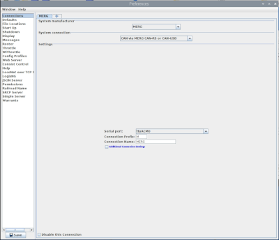
On first launch it will ask for details of the interface. For System manufacturer choose MERG, under System connection choose CAN via MERG CAN-RS or CAN-USB, and for Serial port it is typically ttyACM0. The port number can change if you have other USB devices connect and can even change if you disconnect and reconnect the module after booting the device.
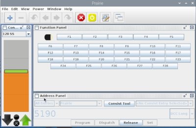
The MERG DCC controller "DCC Command Station" and optionally the "MERG Handset" are detected automatically and need no further configuration. To add the locmotive click on the Roster and choose New Loco. It will prompt you for the name of the decoder. There is an option to Read type from decoder, but this didn't work for me, perhaps it's not supported by the DCC controller. Instead I found the manufacturer of the loco. Note that some manufacturers may use other modules, as I have a Bachmann sound fitted loco which came with an ESU (Electronic Solutions Ulm Gmbh) "LocSound 5 nano DCC Next18". It appears to work even if the decoder is not a full match, but may assign the functions differently.
After adding the loco then you can use the Throttle application to control the loco. Note that it is possible to use DecoderPro to program the decoder in the locomotive, but I had already programmed the address using another controller.
Whilst some devices work using SLiM (Simplified Layout Implementation Model), others will only support FLiM (Full Layout Implementation Model). For the later a computer is needed to perform the configuration. The technical bulletins refer to using the Windows based FLiM Configuration Utility, but there are two alternatives which work with Linux.
The first is to use JMRI which includes a node configuration tool within the MERG menu, but there is also another option called MMC-SERVER which is based on Node.JS and runs across multiple platforms. I used the MMC-SERVER for configuring my modules.
To install MMC-Server you first need Node.JS and NPM the Node.JS Package Manager. As Node.JS is a pre-requisite of npm then this can all be installed using.
sudo apt install npm
After installing Node.JS and npm you can download the software from GitHub MMC-Server. You can either clone using git clone, or download the zip file and unzip that to your home directory. Note that if you download the zip file you should rename the directory from MMC-SERVER-main to MMC-SERVER.
cd ~

unzip ~/Downloads/MMC-SERVER-main.zip

mv MMC-SERVER-main MMC-SERVER
You can then change to that directory to run the npm install and start.
cd ~/MMC-SERVER

npm install

npm start
This will run the software and open a web-browser which will provide the interface for configuring devices. You will need to create a name for the layout but you can normally accept the default for the connection as it will usually automatically connect to the first CANUSB4 module.
To add a device connect it to the CBUS and hold down the FLiM button. You will then need to allocate a node address. I chose numbers starting at 300. There are some configuration options in the Node Variables, for the Solenoid this includes the "On time" for the solenoid. Assuming the point monitor expects a pulse you should ensure that this is not set to zero as that can result in burning out the point motor.
Events can then be added through the event view. These can be entered using a short code, which is useful when also using the CANCAB 2 handset, or a long code which uniquely identifies the different nodes and events / devices.
Each event has event variables which indicate which device / port as well as the operation to carry out. The CANSOLENOID is an updated version based on the CANACC4 are two variables. The first is the particular device (point motor output) and the second is a bitmask that can alter the inputs by flipping bits within the op code.
The CANVServo module kit is based around a universal PCB with different configurations. Using the default configuration then it supports 8 servos (ports 1 to 8) and 8 inputs (ports 9 to 16).
When adding a servo using MMC-SERVER then the Event Variable provides a way to configure how the servo responds to event. However you will also need to go into the Node Variable to set the start and stop positions of the servo.
The inputs can be seen by triggering them. They are created using an event variable based on their port number. For example the first input is on port 9 so triggers event <Node Number> E 9.
To add the events to JMRI first open the corresponding configuration table, eg. for points use the turnouts table. Then add the event using either the shortcode prefixed with a +, or a - to invert the signal.
+22
To add a device using the long address then the address is formed of the node number, then an E followed by the event number.
+300E2
WARNING: This can result in a corrupt PIC configuration and unable to use the module until the PIC is reprogrammed.
The CANVServo can have the firmware upgraded to the VLCB universal firmware. This adds a lot more flexibility, but is also much more difficult to configure. This can be downloaded from: CANMIO Universal Firmware (Merg members.
During the upgrade process I ended up with a corrupt image on the PIC. I was able to fix that by reinstalling an image using the Windows FLiM configuration manager. The MMC-SERVER has that functionality as well but due to a bug it was not an option in the version that I downloaded. That should hopefully be fixed in a future version of MMC-SERVER.
If you are interested in finding out more about MERG, CBUS (based on CANBUS) or VLCB, then see my earlier video / webpage: MERG - Model Electronics Railway Group
Find out more about MERG or about my other model railway projects.
I am considering writing my own library for communicating directly from the Raspberry Pi to the CANUSB4 module.
Also see:
To see future updates please:
Subscribe to the PenguinTutor YouTube Channel
Please view the copyright information regarding use of the circuits.

