- Home
- Learn Linux
- Learn Electronics
- Raspberry Pi
- Programming
- Projects
- LPI certification
- News & Reviews

Google Ads
I have already created a Halloween Project using a Raspberry Pi, a door bell and some home automation. This project is a little simpler and would be suitable for children to have a go at themselves.
The project uses a PIR sensor to detect someone approaching it and in response flashes some LEDs. This is similar to the PIR talking reindeer using a Raspberry Pi, although this uses a different PIR sensor which is easier to wire up and program. I also wired the LEDs directly to the GPIO ports rather than needing a buffer which I used previously.
I did look at using a fan powered by the Energenie power board but the material used let the air through too easily and there wasn't space for a large enough fan to make this work.
This is a project that the whole family can get involved in. There is a little soldering required, but most of this is done using a breadboard and screw terminals.
See the following video for a short introduction
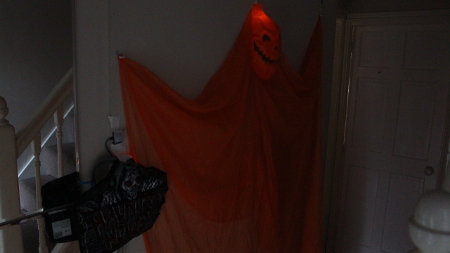
The decorations are standard halloween decorations available from various stores. I have chosen to replace the lights in the pumpkin with my own colour changing LED, drilled holes in the haunted house sign and added an LED inside the head of the pumpkin ghost.
I have already posted details of using a Zilog PIR sensor with the Raspberry Pi, but this time I purchased a different PIR sensor which is now commonly available. There are a few variations on the design, but effectively for this one there is just one pin (in addition to a power supply and ground) which is set to high or low depending upon whether activity is detected. The sensitivity and duration of the status is adjustable using two on-board trimmers (variable resistors)
To avoid having to solder on to the sensor or Raspberry Pi, I used male-to-female jumper leads to a small breadboard (which also had the resistors) and then male-to-female jumper leads to the Sensor. The sensor is mounted on the wall.
I have kept the soldering to a minimum, but long leads are needed between the LEDs and the breadboard, so these needed to be soldered.
Rather than wiring direct to the Raspberry Pi GPIO I used some small breadboards which were also used for the resistors. I used terminal blocks to make it easier to connect the wires from the LEDs.
Raspberry Pi          LED / Sensor       Colour *

GPIO

------------          ------------       --------

pin 2  (+5v)          PIR VCC            Plum

pin 4  (gnd)          PIR Gnd            Blue

pin 7  (GPIO 4)       PIR status         Grey


pin 3  (GPIO 0/2)     LED eye1           White

pin 9  (gnd)          LED Gnd            Black

pin 5  (GPIO 1/3)     LED eye2           Brown

pin 11 (GPIO 17)      Bright LED         Orange

pin 15 (GPIO 22)      LED Red            Red

pin 16 (GPIO 23)      LED Green          Green
* The colour just happens to be the colour of the wire that I used. Any colour can be used.
The software can be downloaded from:
or by issuing:
wget http://www.penguintutor.com/software/raspberrypi/halloween2.tgz
Unzip the files into the pi home directory using:
tar -xvzf halloween2.tgz
The python script can be run from the command line to test it is working using:
sudo ./halloween2.py
To make it run automatically add the following entry into /etc/rc.local:
cd /home/pi/halloween2 && /usr/bin/python halloween2.py &
#!/usr/bin/python

import RPi.GPIO as GPIO

import time


# pins are labelled using board for compatibility with rev 1 / rev 2

pirPin = 7

eyePin1 = 3

eyePin2 = 5

brightPin = 11

redPin = 15

greenPin = 16


GPIO.setmode(GPIO.BOARD)

GPIO.setup(pirPin, GPIO.IN, pull_up_down=GPIO.PUD_DOWN)


GPIO.setup(eyePin1, GPIO.OUT)

GPIO.setup(eyePin2, GPIO.OUT)

GPIO.setup(brightPin, GPIO.OUT)

GPIO.setup(redPin, GPIO.OUT)

GPIO.setup(greenPin, GPIO.OUT)


while True:

	time.sleep(0.1)

	if GPIO.input(pirPin):

		print "Motion detected"

		GPIO.output (eyePin1, 1)

		time.sleep (1)

		GPIO.output (eyePin2, 1)

		time.sleep (1)

		GPIO.output (eyePin1, 0)

		GPIO.output (eyePin2, 0)

		GPIO.output (brightPin, 1)

		time.sleep (0.5)

		GPIO.output (redPin, 1)

		time.sleep (1)

		GPIO.output (greenPin, 1)

		time.sleep (1)

		GPIO.output (redPin, 0)

		time.sleep (1)

		GPIO.output (greenPin, 0)

		time.sleep (0.2)

		GPIO.output (brightPin, 0)

		time.sleep(5)
This is a fun easy project that most should be able to do. If used indoors then there is no need to waterproof the parts. The one thing I did find was that the tri-colour LED is not very bright, whilst I used a bright LED for the pumpkin ghost head the tri-colour is just a standard one. It looks a bit better in low light, but could do with being brighter.
See the guides and blog posts relating to the Raspberry Pi.
Raspberry Pi outdoor Halloween Project
Please view the copyright information regarding use of the circuits.

