- Home
- Learn Linux
- Learn Electronics
- Raspberry Pi
- Programming
- Projects
- LPI certification
- News & Reviews

Google Ads
Home electronics can open up a new dimension in home automation especially when used with an Arduino or Raspberry Pi. There is however a very real danger when using mains electricity, including risk of electricution and danger of electrical fires if the components are not rated correctly. See this guide on risks when working with electricity. This design greatly reduces any risk by avoiding the mains electricity by using commercially available remote control plugs or light fittings. In particular the plug sockets (shown below) do not need any work to be done on the house electrical system; light fittings are also available which need to be installed by a competent adult or qualified electrician.
The project is based on the Raspberry Pi as an embedded computer, but I have also created a guide for using an Arduino for home automation.
Update When I created this guide this was the easiest way that I found to interface with mains sockets. Since then Energenie has created a Raspberry Pi add-on board that can be used to turn sockets on and off as well. There are pros and cons for both versions, but I suggest you take a look at: Home Automation using the Raspberry Pi and Energenie add-on module.
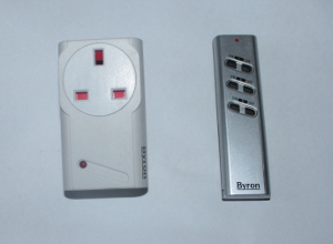
This circuit uses a remote control socket or other home automation remote control devices. The sockets are available as a plug adapter that goes between the normal wall socket and the plug for the device to control. They are available as standard on/off switches or with a dimmer for controlling a light. Either will work for this circuit, but a dimmer socket can only be used for lights and even then only certain light bulbs that are "dimmable".
Please note that there is no in-built security or protection from neighbours with similar controls. There are usually multiple channels (in the devices I used 4), but there is a risk that others may select the same channel. As such these should not be used for anything that could pose a risk if turned on or off without notice. For example do not use for a critical light (eg. staircase or cellar) where it may be dangerous if the light turned off unexpectedly. Check the instructions with the particular home automation device for more details.
I have used these for Christmas fairy lights and other decorative lighting, and as an additional entry light, but there is far more potential particularly when using the Raspberry Pi.
The down-side of this project is that it will invalidate your warranty for the remote control and the soldering can be quite difficult (depending upon the type of remote control), although the cost of an additional remote control is usually quite reasonable, or even the cost of buying a set of sockets is still the fraction of the cost of a full home automation system.
I used a Byron remote control socket set available from B&Q. These were originally bought to make it easier to turn Christmas fairy lights on without crawling under the Christmas tree. B&Q still sell the socket sets, but they no longer sell the light fittings. The light fittings normally come with a wall mounted single on / off switch rather than the six button remote control so you may wish to purchase a remote control to go with them. There are other makes available from various suppliers including DIY stores or electrical retailers. Typically plug-in sockets cost about £15 to £25 for between one and three sockets (perhaps a little more if it includes a dimmer socket), but you may need to buy an additional set or remote control if you also want to use these with the remote control as it will not be possible to use the remote control as a hand held remote control after making the changes. You need a device with a basic on/off remote control and not a timer or other advanced remote control (although you can still continue to use them alongside this project). The one shown on the right appears to be a newer version of the remote control that I bought some time ago - I don't know if this will be any easier or harder to solder to (see later). The remote control shown later is a similar button design, but benefits from an additional master on and off buttons that can control all three devices simultaneously.
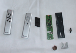
Rather than having to create a wireless circuit to match the specification of the remote control the easiest way is to modify the existing remote control so that it can be controlled by an external circuit (typically actuated by an Arduino or Raspberry Pi). Each of the buttons on the remote are push to close switches, so we can connect a relay across each of the switches to emulate a user pressing each button. Before taking the remote control apart make sure it works normally first. It's very frustrating to spend time trying to diagnose your circuit if it's connected to another circuit that didn't work in the first place.
The remote control is unscrewed to access the internal circuit board. On these remote controls the remote can be one of 4 different settings which is chosen by a switch on the back. In this case I have set it to switch "C" (most users will leave at the default "A" position which is best avoided), so I've soldered a wire in the 3rd position shown in red on the top image. Then on the front side a wire needs to be soldered on to each side of each switch you want to control. In this particular case there is a matrix configuration for the switches so several of the switches share the same connection, reducing the number of wires required (see the artificial colouring I've added on the diagram below).
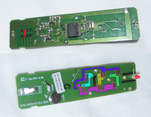
Using the colours as a guide to switch device one on needs a connection from the green track (switch one common point) to the purple track (commn track for the on buttons), to turn it off needs a connection between the green and the pink coloured tracks. Likewise replace green with yellow for device 2 etc. Apologies to anyone that is unable to see the different colours, but you can instead look at the buttons on your particular remote control and follow where the tracks go (which will be required if using a different model anyway).
| On | Off | |
|---|---|---|
| Device 1 | green to purple | green to pink |
| Device 2 | yellow to purple | yellow to pink |
| Device 1 | blue to purple | blue to pink |
For this particular remote control then the soldering was the hardest part. I'd recommend this for those with some experience of soldering. Other remote controls may be easier to solder to.
For the switch on the rear I was able to solder wires direct to the switch contacts. For the other switches I tried scraping away some of the coating on the circuit board, but was unable to get the solder to stick to the track. I therefore soldered the wires to the holes where the tracks go from one side of the double sided circuit board to the other. Failing that it may have been possible to solder to the pin of the integrated circuit on the board, but I would only do that as a last resort as it is a SMD device and so there isn't much lead to solder to and there is a risk of damaging the IC.
I used devices one and three, but that is only because that is what I'd already set my corresponding devices to; I used device two for another device that I didn't want controlled by the Raspberry Pi. Note that when I refer a device this can actually be multiple sockets / devices, but are all programmed to respond to the same signal.
This remote control normally uses a 3V button cell battery, but it was not possible to hold it in place without the case, so additional wires were soldered on to those to supply 3V from two AA batteries in a battery holder. The photo below shows the remote control circuit board complete with wires soldered onto it.

To emulate a user pressing the switch I am using a relay. A relay is a switch that changes position when current is applied through a magnetic coil. Essentially you apply a voltage to one pair of contacts and it causes a switch across the other two contacts to close. There is no electrical connection between the input signal and the output so there is no risk of anything from the remote control damaging the Raspberry Pi. As the current in the remote control is so small then a reed relay is sufficient. These are similar to standard relays, but use less power to switch them on.
The GPIO provides only 3.3V. Whilst it is possible to get reed relays that work at 3.3V the GPIO ports can only supply a small amount of current (approx. 50mA for all ports in use), which is just a little more than a 3.3V reed relay requires. Whilst this may be sufficient to switch a pair of reed relays as long as only one is on at a time there is no protection for the GPIO ports and hence the Raspberry Pi so I am therefore using a Pi Face digital which provides protection for the GPIO and allows the use of the more common 5v reed relays. Alternatively it would be possible to use a transistor switch circuit to connect the relays to the GPIO ports.
The Pi Face is a digital input board which provides a way of connecting digital components to the Raspberry Pi. It provides protected inputs, open collector outputs (which can be used for circuits with higher than the 3.3V that the GPIO can use) and relays.
The Pi Face has two relays on the board which can be used instead of adding these reed relays, but as there are only two relays that is only sufficient for one set of devices (the first for on, the second for off). In this case I've left the relays for other circuits and I'm instead using the open collector outputs to switch reed relays.
The reed relay that I used is the HE751A0510. This is a 5v reed relay that uses about 10mA. It can therefore be powered directly from the 5v power supply on the Pi Face board.
The circuit diagram below shows how each reed relay connects to the PiFace.
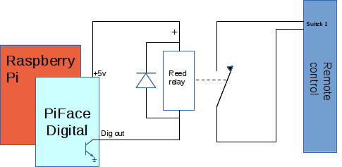
I used four relays, which is sufficient for two devices with an on and off for each. These connect to four different outputs from the Pi Face Digital. These can use the outputs from ports 2 upwards as ports 0 and 1 have been left to be used for another purpose using the two onboard relays. In this example I've used the following outputs:
Pin 4 - device 1 on
Pin 5 - device 1 off
Pin 6 - device 3 on
Pin 7 - device 3 off
Note that there is a diode shown in the circuit diagram connected in the reverse direction across the relay coil. This is required due to the back EMF produced when the magnetic coil is de-energised. The particular model of reed relay used has the diode included within the package. The last two digits denote the features of this relay which in this case indicates that it "includes Coil Suppression Diode". If using a different reed relay then an external diode needs to be connected. Normally a schottky diode should be used as a suppression diode, although with a reed relay any normal diode would be sufficient.
The complete circuit has the four reed relays mounted on a breadboard. I have also used some terminal connectors to connect to the flexible wire used to the breadboard

The latest Raspberry Pi NOOBS images include the appropriate python libraries for the PiFace digital. By default the device driver is disabled to prevent conflicts. The following is required to enable the driver.
Edit the file /etc/modprobe.d/raspi-blacklist.conf and remove the line containing the entry spi-bcm2708 .
Then add the file /etc/udev/rules.d/50-spi.rules with the entry:
KERNEL=="spidev*", GROUP="spi", MODE="0660"
This will need a reboot to load the driver.
This sample python code shows how the mains powered equipment can be switched using the Raspberry Pi. This example just switches one of the devices on and off.
#!/usr/bin/env python


from time import sleep

import pifacedigitalio


# Time that the button is pressed for

BUTTON_PRESS_TIME = 0.5  # seconds


# Device pin numbers

DEVICE_1_ON = 4

DEVICE_1_OFF = 5

DEVICE_2_ON = 6

DEVICE_2_OFF = 7


def main():

    # Setup PiFace

    pifacedigitalio.init()

    piface = pifacedigitalio.PiFaceDigital()


    # switch device 1 off

    print "Device 1 off"

    # Turns the relay on (switches device off)

    piface.output_pins[DEVICE_1_OFF].turn_on()

    sleep(BUTTON_PRESS_TIME)

    # Turns the relay off

    piface.output_pins[DEVICE_1_OFF].turn_off()


    # Delay before we turn it on

    sleep(1)


    # Turn device on

    print "Device 1 on"

    piface.output_pins[DEVICE_1_ON].turn_on()

    sleep(BUTTON_PRESS_TIME)

    piface.output_pins[DEVICE_1_ON].turn_off()


    # Leave device on for 5 secs

    sleep(5)


    # Turn device back off

    print "Device 1 off"

    piface.output_pins[DEVICE_1_OFF].turn_on()

    sleep(BUTTON_PRESS_TIME)

    piface.output_pins[DEVICE_1_OFF].turn_off()


if __name__ == "__main__":

    main()
The code starts by initialising the PiFace creating a PiFace object which I've called piface. I have then turned the device off before turning it on. This is because on the Byron dimmable units then pressing on when it is already on will cause it to switch into dimmer mode. By switching it off first then it prevents that. Another thing to consider is how long the button is pressed as for some devices holding the button down for a long period of time has the same effect. This is why I have set BUTTON_PRESS_TIME so that this can be changed if more appropriate.
Another thing to bear in mind is that turn_off and turn_on refers to the port on the PiFace and hence the relay and not the mains powered device. It is perhaps better put into a function which includes the turn_on, the delay and the turn_off.
See the pifacedigitalio project for more information on communicating with the Piface from Python.
The code above illustrates how to turn devices on and off, but isn't particularly useful on it's own. So here are some suggestions for practical uses:
These are just a few examples, but there are lots of other ways this can add home automation to mains powered devices. Please keep in mind the safety implications mentioned earlier and also that if a heater / radiator is used that it is positioned so that it does not pose a fire risk.
These examples are beyond the scope of this particular guide, but I will provide details of another real project using this setup in future. You can also work these into a practical project with reference to some other guides; for example try a Google search for Raspberry Pi speach recognition for inspiration on how you could add voice activation for that ultimate Star Trek like automation.
* Note that the lack of real time clock on the Raspberry Pi means that there is no independant clock that can provided guarenteed actual time. It is possible to get the time from an NTP time server if the Raspberry Pi is connected to the Internet. Normally connecting to the Internet via the ethernet port will be sufficient, but you may want to include a sanity check within the code. Or you could add a real time clock board for the Raspberry Pi (it will need an additional breakout for the GPIO so that it can be connected at the same time as the Piface).
This has provided the details of how to control power to mains electrical devices without making any physical connections to the mains electricity components. There are still some safety factors that need to be considered, but it's much safer than say installing your own relay directly onto a mains power lead.
This still needs some programming and optionally additional hardware to give it a more practical use, but it has provided sufficient to get the example circuit up and running. I'd be interested in hearing what other people make with regards to home automation using this technique.
Also consider the Energenie home automation power socket Raspberry Pi add-on board.
Please view the copyright information regarding use of the circuits.

