- Home
- Learn Linux
- Learn Electronics
- Raspberry Pi
- Programming
- Projects
- LPI certification
- News & Reviews


This is the reference guide to the Raspberry Pi GPIO ports. For an overview and projects relating to the Raspberry Pi then see the Raspberry Pi Tutorials page.
 The Raspberry Pi is an ideal computer for use in physical computing thanks to its GPIO connector. This is a mulit-way male connector with either 26 or 40 pins. These pins can supply power, logic level input and output (3.3V only) and other connection types such as PWM, SPI, I2C and Serial. This flexibility provides many different ways to connect to the real world through electronic componenets.
Confusingly the pins can have different numbers assigned to them depending upon whether you look at their physical position or on how they are used.
The GPIO connector can be used as a single connector (eg. by connecting a HAT or using a 40-way connector), but they are also individual pins which can be individually numbered. With the SD card slot positioned at the top then the top-left is pin 1 and top-right is pin 2. They are then numbered from left to right as you work your way down the connector. This is sometimes referred to as the board pin number which is useful for identifying the physical pin. When writing code then they are more often referred to by a different number.
The connectors mostly connect directly to the pins on the Broadcom processor (CPU). As a result many have a GPIO reference which relates to how it connects to the processor. This is the number that is most commonly used when writing code to refer to the GPIO ports.
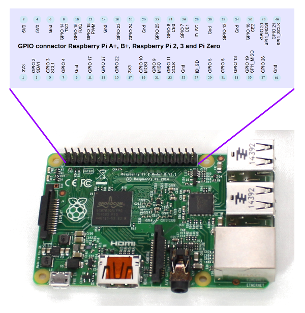
The diagram below shows how the pins are physically positioned and some for the different purposes for the pins.

The table below shows the ports and the primary and altenative uses.
|
Pin number |
GPIO port |
Alternative function |
Comments |
|
1 |
|
3.3V power supply |
|
|
2 |
|
5V power supply |
|
|
3 |
GPIO 2 |
SDA1 (I2C data) |
Changed from revision 1 boards |
|
4 |
|
5V power supply |
|
|
5 |
GPIO 3 |
SCL1 (I2C clock) |
Changed from revision 1 boards |
|
6 |
|
Ground |
|
|
7 |
GPIO 4 |
|
|
|
8 |
GPIO 14 |
Serial / console TXD |
Serial transmit |
|
9 |
|
Ground |
|
|
10 |
GPIO 15 |
Serial / console RXD |
Serial receive |
|
11 |
GPIO 17 |
|
|
|
12 |
GPIO 18 |
PWM |
Pulse Width Modulation |
|
13 |
GPIO 27 |
|
Changed from revision 1 boards |
|
14 |
|
Ground |
|
|
15 |
GPIO 22 |
|
|
|
16 |
GPIO 23 |
|
|
|
17 |
|
3.3V |
|
|
18 |
GPIO 24 |
|
|
|
19 |
GPIO 10 |
MOSI (SPI) |
SPI Master Output, Slave Input |
|
20 |
|
Ground |
|
|
21 |
GPIO 9 |
MISO (SPI) |
SPI Master Input, Slave Output |
|
22 |
GPIO 25 |
|
|
|
23 |
GPIO 11 |
SCLK (SPI) |
SPI clock |
|
24 |
GPIO 8 |
CE0 (SPI) |
Chip Enable (slave select) |
|
25 |
|
Ground |
|
|
26 |
GPIO 7 |
CE1 (SPI) |
Chip Enable (slave select) |
|
27 |
|
ID_SD |
For HAT EEPROM |
|
28 |
|
ID_SC |
For HAT EEPROM |
|
29 |
GPIO 5 |
|
|
|
30 |
|
Ground |
|
|
31 |
GPIO 6 |
|
|
|
32 |
GPIO 12 |
|
|
|
33 |
GPIO 13 |
|
|
|
34 |
|
Ground |
|
|
35 |
GPIO 19 |
SPI1_MISO |
|
|
36 |
GPIO 16 |
CE2 (SPI) |
Chip Enable (slave select) |
|
37 |
PIO 26 |
|
|
|
38 |
GPIO 20 |
SPI1_MOSI |
|
|
39 |
|
Ground |
|
|
40 |
GPIO 21 |
SPI1_CLK |
|
Also see: Raspberry Pi tutorials and projects.
Please view the copyright information regarding use of the circuits.