- Home
- Learn Linux
- Learn Electronics
- Raspberry Pi
- Programming
- Projects
- LPI certification
- News & Reviews

Google Ads
 The Arduino is like an electronic hobbyists dream come true. A low cost microproccessor based circuit that can run from USB or an external supply, it is open source and works with Linux. For more details about the Arduino see the Arduino reference.
To get started you build a simple circuit using a Light dependent resistor (LDR). This is going to replicate the low light sensor project, but also show some of the additional flexibility of the Arduino vs. discrete components.
To follow along you will need:
To get started download and install the Arduino IDC software from the Arduino website. This can be installed onto most computers. I have tried this on Kubuntu and Xubuntu Linux. Full instructions for installing depend upon your distribution (or operating system) and are included on the download website. The video below goes through this process.
The Arduino is connected via a USB cable. There is also a connector for an external power supply if desired. This can be connected to either a battery connector or to a plug-in transformer (wallwart). If using an external supply the voltage should be between 7 and 12V, regulated DC supply; a 9V power supply would be ideal. The connector needs to be a 2.5mm DC connector with centre positive. If you have an original Diecimila then you will need to move a jumper on the Arduino to switch between using the USB and external power supply, but for the more recent models this is automatic.
Before we add the light dependent resistor lets start with an even more basic circuit. This circuit really doesn't need the Arduino at all, but it can be used to illustrate some of the basics of how the Arduino works and we'll be using as the starting point for the more complex circuit later.
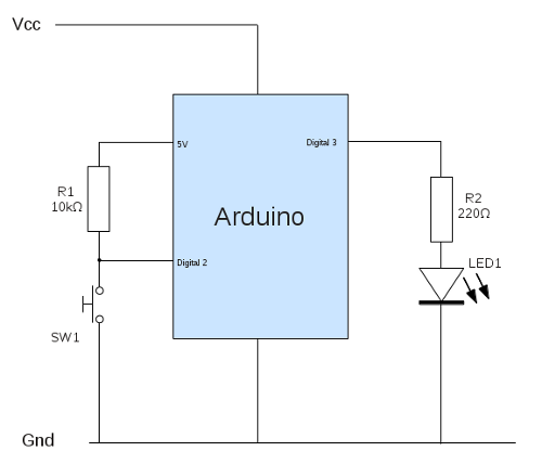
A simple switch circuit diagram is shown below:
This circuit is going to perform a similar function to the basic switch circuit, but with an Arduino thrown in for good measure.
The components R1 (10kΩ resistor) and sw1 (push to make switch) form the input to the Arduino. The 5v supply voltage is taken from the Arduino (port labelled 5V) and the input is to Digital pin 2. Pins 0 and 1 have been deliberately avoided as they are also used for the communication with the USB port. Whilst it is possible to use them in this particular circuit using those pins can cause further complications with other circuits, when communicating with a computer over the USB port.
The 5v supply is taken from the Arduino as the supply voltage may be higher than 5v, whereas that pin on the Arduino is from the same regulated supply that the power to the ATMega chip is provided.
R1 is a pull-up resistor which connects the Arduino input pin to a high voltage (logic 1) when the switch is in the open (default) position. It needs to be sufficiently high to restrict current flowing back to ground when the switch is closed, but still to allow sufficient current into the Arduino when the switch is open. In fact this resistor is not actually needed as the ATMega chip includes built-in 20k&Oomemega; resistors which can be enabled instead, but it is easier to understand with a physical resistor that you can see. I will continue to use an external pull-up resistor for some other circuits where it helps with understanding the circuit.
When the switch sw1 is closed the input to the Arduino is pulled down to the ground (0v) supply providing a low signal to the Arduino. Current will still flow through the resistor, but will then return back to the power source through the ground connection. The pull-up resistor has been selected to ensure that the current (and hence the energy used) is low.
This means that with the switch open (default) the input pin is held to a logic high and when the switch is closed the input pin goes low.
The output pin (pin 3) is connected through resistor R2 (220Ω) into the LED. The voltage drop across an LED is typically 2v (depends upon type), so the 220Ω resistor will restrict the current to about 14mA which is well within the normal operating range. This resistor is not strictly neccessary as the Arduino is unlikely to provide more current than an LED requries, but it is good practice to design to limit the current through an LED.
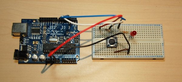
The complete circuit has been build on breadboard, as shown in the photo below.
When using the Arduino it's not just enough to create the physical circuit, but we also need to write the code that is to run within the ATMega processor.
 The code that runs on the Arduino is written in the C programming language. Don't worry if you haven't programmed with C before, although a bit of programming experience will be useful. I'll explain the code in detail, but you may need to learn a bit more programming when creating more complex code in future. The structure of C is similar to other programming languages such as Java or C#.
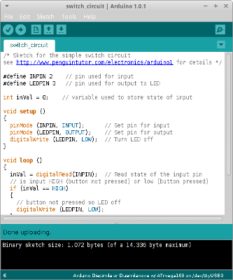
To get started load the Arduino IDE which is an executable called Arduino (on my system I installed into the /opt directory so it can be run as /opt/arduino-1.0.1/arduino
The code for the Arduino is referred to as a sketch. First choose a name for your sketch and Save using that as the filename. In my case I've called it switch_circuit. The IDE will automatically create a directory and a file called switch_circuit.ino
/* Sketch for the simple switch circuitsee http://www.penguintutor.com/electronics/arduino1 for details */ #define INPIN 2 // pin used for input#define LEDPIN 3 // pin used for output to LED int inVal = 0; // variable used to store state of input void setup (){ pinMode (INPIN, INPUT); // Set pin for input pinMode (LEDPIN, OUTPUT); // Set pin for output digitalWrite (LEDPIN, LOW); // Turn LED off} void loop (){ inVal = digitalRead(INPIN); // Read state of the input pin // is input HIGH (button not pressed) or low (button pressed) if (inVal == HIGH) { // button not pressed so LED off digitalWrite (LEDPIN, LOW); } else { // button pressed so LED on digitalWrite (LEDPIN, HIGH); }}You can just copy and paste this into the IDE. Then use the upload button to compile and send it to the Arduino (assuming it's connected to the PC). Here's an explanation of what the code does.
Lines 1 and 2 are comments. Comments can be a block comment marked between /* and */, which can span multiple lines or a line comment beginning with // which are interpretted as comments from the marker until the end of the line.
Line 3 is empty - multiple blank spaces including lines tabs etc are generally ignored in C programming (this is different to python where tab positions do count). White spaces are useful to help make code easier to read.
Lines 4 and 5 define which pin we are using for the input and output from the Arduino. It is recommended that these are either defined (which is handled by the pre-processor so does not use any memory in the compiled code) or as a variable (which uses memory, but allows it to be changed during the code - if desired).
Line 7 is a variable. In this case it is an integer so can contain a number between -32768 and 32767. In this case we could have used a byte instead which holds between 0 and 255, or indeed a boolean (but we will be using this differently in a future sketch).
From line 9 to 14 is the setup function. This is code that is run once when the Arduino is first initialised (switched on / reset). Lines 11 and 12 set eha appropriate digital pins to in / out and line 13 is used to set the output to the LED to low (off).
The rest of the code (in this particular example) is in the loop function which is from lines 16 to 30. The code in the loop function will be repeated over and over again until the Arduino is powered off. First (line 18) the state of the input pin is read and stored in the variable defined earlier. If the pin is set to high / logic 1 (line 20) then the output is set low (line 23). Otherwise it's set high (line 28).
The result is that when pressed (low input) the LED is on (high output), and when the switch is released (high input) the LED is off (low output).
Once installed onto the Arduino the USB cable is just providing power. It can instead be removed and power connected to the 2.5mm power socket (and jumper changed if using an old Diecimilia) if desired.
This circuit is now complete, but it's not really that useful. After all we could have achieved the same by just connecting the LED directly to the switch. Next we'll look at changing the switch for other sensors and communicating with a computer.
Please view the copyright information regarding use of the circuits.

