- Home
- Learn Linux
- Learn Electronics
- Raspberry Pi
- Programming
- Projects
- LPI certification
- News & Reviews

Google Ads
The video below is a demonstration of how multiple devices can be connected using the same SPI bus. In this case a pair of OLED displays based around the SSD-1306
The OLED display is based around a SSD1306 integrated circuit. The IC can be used with I2C or SPI depending upon the PCB that it is mounted on. Both types can be used with a Raspberry Pi Pico, but one issue with I2C is that the address is normally fixed, so it's not possible to connect two displays to a single bus and control them independently. Some options do exist, including using two separate I2C channels on the Pico, or in some cases cutting through tracks on the OLED PCB, but instead I chose to use the SPI version.
SPI is a serial protocol, which means that data is sent one bit at a time down a wire. Unlike the serial protocol used for USB which is asynchronous, SPI is synchronous. It uses a clock signal so that all devices can stay in sync and it's full-duplex allowing data to be transferred in both directions at the same time. It's also a bus technology which means you can add multiple devices on the same serial ports.
There can be several secondary devices, but only a single main device controlling the bus. Communications are full-duplex and bidirectional. There is not fixed meaning for how the data is formatted (only the way it is transmitted). If using an Arduino you can define your own protocol, or if communicating with an integrated circuit (IC) then the protocol is provided by the datasheet for that particular integrated circuit.
The image below shows how one main device can control the SPI communications with three secondary devices.
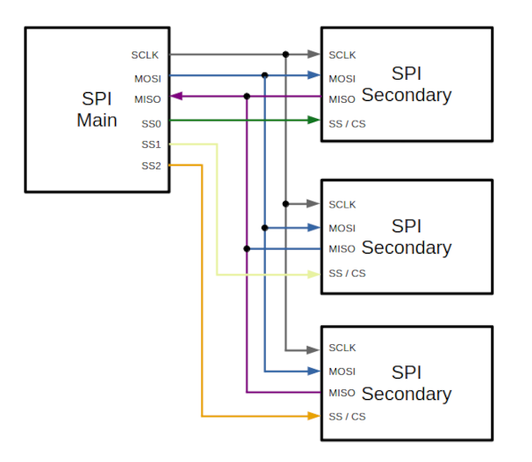
There is a single SPI Clock signal (SCLK) which goes from the main device to all the secondary devices. There is a bus connection labelled MOSI (main out, secondary in) which handles communication from the main device to all the devices, and MISO (main in, secondary out) which is used for the data transferred from the secondary device to the main device. All these 3 lines are shared between all devices, but there is an additional secondary select which enables just one secondary device at a time. This needs one additional line per device. The secondary select can sometimes be called chip select (CS) or chip enable (CE).
So based on this you can connect multiple devices to a single SPI bus, needing 3 pins for the bus, plus one for the chip select for each device.
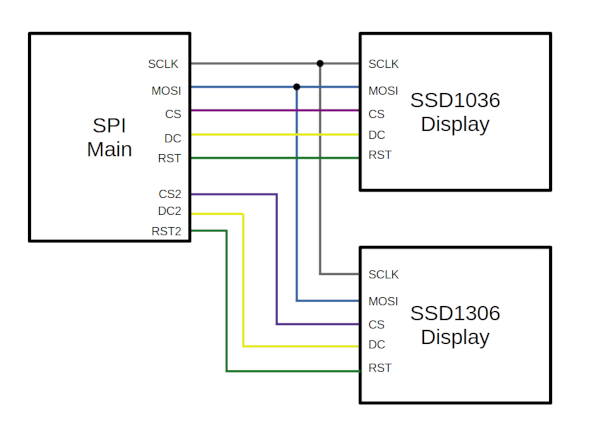
Having looked at the theory, we can look at the SSD1306, which doesn't quite match what I've said before. Firstly the display receives information, but does not need to send anything back to the controller, so no need for the MISO pin. That's one less, but then as well as the chip select the display also needs a Reset and Data / Control pin. So in reality it needs 2 pins for the bus (although if using other bidirectional devices on the same bus you'll need 3), one pin for chip select and then two additional pins, because of the additional pins needed for the SSD1306.
You can still add other SPI devices to the same bus, but you need to allocate another chip-select pin and may need to add the MOSI pin if the new secondary device needs to send information back to the main controller.
If you are running short of pins then there is a workaround, or at least it appears to work for me. The reset pin doesn't appear to be required, and if you connect it directly to a logic high (VCC) then that appears to work.
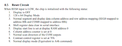
The library does perform a reset when first initializing, but otherwise it doesn't appear to be used. Reading the datasheet it says that a reset performs a number of operations including setting the resolution and putting it into normal display mode.
You still need a pin to be assigned for the library to work, but I have found if you set it to the same as the chip select pin then that works and doesn't need any additional pins. You may want to test this in your own setup before relying on it.
Below are the port allocations I used to connect from the Raspberry Pi Pico to each of the SSD1306 SPI OLED displays.
| Raspberry Pi Pico GPIO | Display 1 pin | Display 2 pin | Variable Name | Comment |
|---|---|---|---|---|
| 18 | SCK | SCK | SCLK | SPI Clock |
| 19 | MOSI | SDA | MOSI | SPI Main Out Secondary In / Serial Data |
| 16 | CS | CS | Chip select device 1 | |
| 17 | DC | DC | Data / Control device 1 | |
| 20 | RES | RST | Reset device 1 | |
| 21 | CS | CS2 | Chip select device 2 | |
| 22 | DC | DC2 | Data / Control device 2 | |
| 13 | RES | RST2 | Reset device 2 |
Below is some example code to test it is working. You will also need to upload the file ssd1306.py to the Pico. The library is available from github: ssd1306.py.
# Demo for SSD1306 with two displays connected

from machine import Pin, SPI

import ssd1306

import time


# Uses SPI port 0

spi_port = 0

SCLK = 18

MOSI = 19

CS = 16

DC = 17

RST = 20

CS2 = 21

DC2 = 22

RST2 = 13


WIDTH = 128

HEIGHT = 64


spi = SPI(

    spi_port,

    baudrate=40000000,

    mosi=Pin(MOSI),

    sck=Pin(SCLK))

print(spi) # Not essential can remove


oled = ssd1306.SSD1306_SPI(WIDTH,HEIGHT,

    spi,

    dc=Pin(DC),

    res=Pin(RST),

    cs=Pin(CS),

    external_vcc=False

    )


oled2 = ssd1306.SSD1306_SPI(WIDTH,HEIGHT,

    spi,

    dc=Pin(DC2),

    res=Pin(RST2),

    cs=Pin(CS2),

    external_vcc=False

    )


# Clear the oled display in case it has junk on it.

oled.fill(0)


# Add some text

oled.text("This is display", 5, 6, 1)

oled.text('Number 1', 5, 16, 1)

oled.text("Which is Yellow", 5, 25, 1)

oled.text('and Blue', 5, 36, 1)

oled.text('Up to 6 lines -', 5, 46, 1)

oled.text("15 characters!", 5, 57, 1)


# Finally update the oled display so the text is displayed

oled.show()


oled2.fill(0)

oled2.text("This is display", 5, 6, 1)

oled2.text("Number 2", 5, 16, 1)

oled2.text("This is white", 5, 25, 1)

oled2.text('only, but has ', 5, 36, 1)

oled2.text('same 6 lines &', 5, 46, 1)

oled2.text("15 characters!", 5, 57, 1)


oled2.show()
Please view the copyright information regarding use of the circuits.

